YOUR GUIDE TO MEASURING A SUCCESSFUL UV-C PROJECT
The UV-C Blueprint is your go-to tool for guiding how to properly spec a UV-C project, ensuring that engineers receive all the critical details they need. This form walks you step-by-step through system configurations, part selections, and measurement inputs to make sure you’re delivering the right information every time. We’ve also included a detailed guide on how to measure and spec products, helping you confidently determine requirements from the very first dimension to final spec.
If at any point you can’t quite ‘find your way into the light’, please contact one of the Blue Light Crew to guide you the rest of the way. [CLICK HERE]

THE UV-C ‘BLUE’PRINT PROJECT GUIDE
CLASSIC EDITION
Here is the is the old-school version — ready to print and fill out with your favorite pencil or pen. Perfect for those greasy fingerprints and scribbled notes in the margins.
DOWNLOAD THE BLANK FORMQUICK START REFERENCE
HOW TO MEASURE
- Airflow (CFM): Record rated unit airflow from the manufacturer’s nameplate or submittal data.
- Coil Dimensions: Measure height (H) and width (W) of each coil face. Repeat for multiple coil banks.
- Number of Coils: Note coil orientation (stacked, side-by-side) to determine lamp overlap requirements.
- Access Doors: Count service doors to define lamp access points and interlock switch placement.
- Cabling: Estimate total footage and number of cable runs required to connect fixtures to available power. Note: IP67 connectors are a standard 4ft length.
HOW IT WORKS
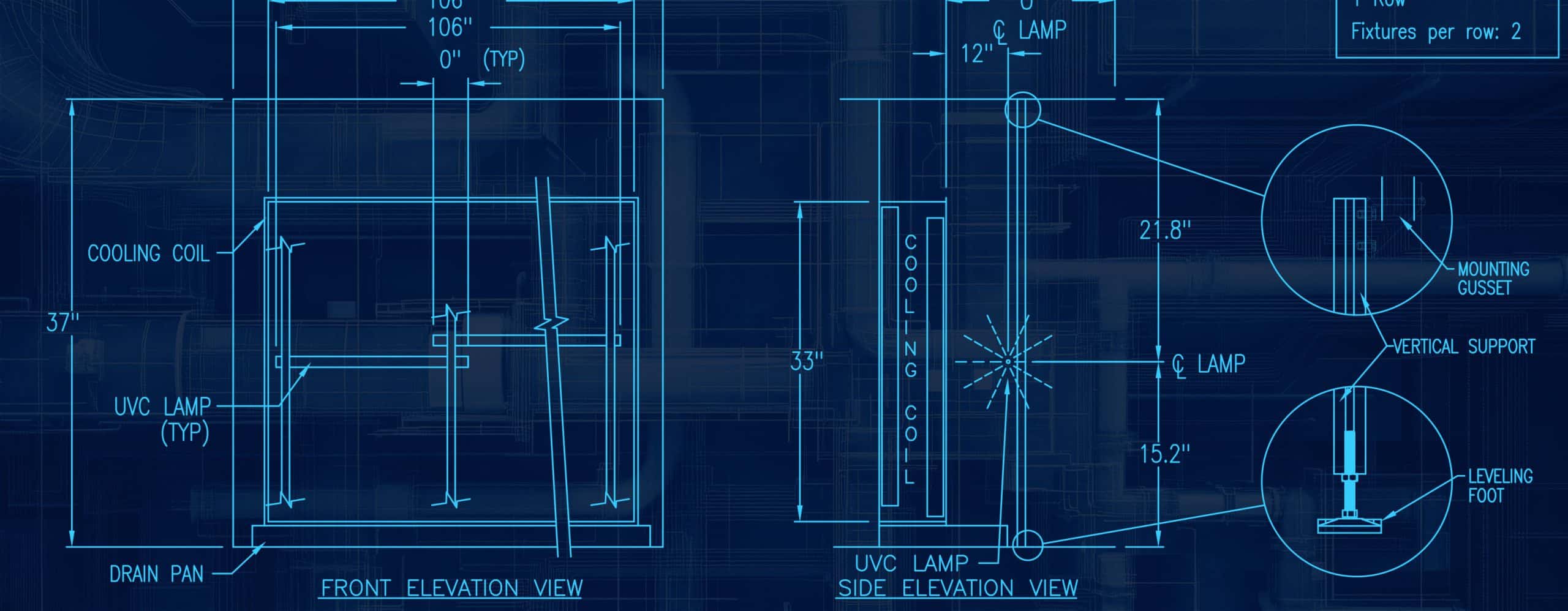
UV-C lamps emit germicidal radiation at 253.7 nm, continuously irradiating coil and plenum surfaces. To achieve effective coil surface cleaning, ASHRAE Handbook Chapter 60.8 recommends a minimum threshold of 50–100 µW/cm² across the entire coil face. Translating this into practical design, UV Resources applies a rule of approximately 7.5 watts of lamp power per square foot of coil surface area. Fixtures are typically mounted at a distance of 12 inches from the coil, while reflective plenum materials (galvanized steel, stainless, aluminum) can increase dosage by 40–75%, ensuring uniform irradiance even at coil edges and corners.
WHY IT MATTERS
Fouled cooling coils restrict airflow, increase static pressure, and reduce heat-exchange efficiency. Documented field studies confirm that UV-C exposure can reduce coil pressure drop and increase heat transfer, restoring near “as-built” performance.
Properly specified systems help:
- Maintain coil cleanliness and airflow conditions
- Improve indoor air quality (IAQ)
- Reduce energy use by up to 25%
- Extend equipment life and minimize unscheduled maintenance
By supplying complete and accurate field data, sales teams enable engineers to specify correct lamp types, quantities, and configurations, eliminating design uncertainty and ensuring cost-effective performance.
(AIRFLOW) CFM
Airflow, measured in cubic feet per minute (CFM), is a key input for proper UV-C sizing. Higher air velocities reduce the time air and surfaces are exposed to UV-C, which lowers dosage. In fact, at ~500 fpm and 55°F, UV-C lamp output is typically reduced by about 50%.
- Measure CFM: This is usually available from the AHU nameplate, submittals, or building automation system.
- Why it matters: Accurately reporting airflow helps account for de-rating and ensures the correct number of lamps are specified.
- Tip: If airflow is unknown, provide fan horsepower or AHU model details so CFM can be estimated.
Supplying accurate CFM ensures the system is designed to deliver the proper irradiation across the coil face, even under real operating conditions.
HOW TO MEASURE A PLENUM
- Height (H): Top to bottom of plenum interior
- Width (W): Left to right across plenum interior
- Depth (D): Coil face to opposite wall (or obstruction)
- Coil Banks: Record if coils are stacked (vertical) or side-by-side (horizontal)
- Access Points: Note the number and placement of access doors for lamp service/inspection
Accurate plenum measurements ensure proper lamp placement, clearance, and service access.
PLENUM MATERIAL
The plenum surface material impacts how UV-C energy reflects and distributes within the air handler. Surfaces with higher reflectivity amplify UV-C dosage, extending coverage to coil edges, plenum corners, and shadowed areas. This multiplier effect improves microbial inactivation rates and ensures that ASHRAE’s minimum irradiation levels are met more uniformly across the coil surface.
- Stainless Steel → ~1.40x multiplier
- Galvanized Steel → ~1.50x multiplier
- Aluminum → ~1.75x multiplier
Accounting for plenum reflectivity allows more precise lamp sizing, ensuring system efficiency without over- or under-specifying UV-C output.
HOW TO MEASURE A COIL
To size UV-C lamps correctly, you’ll need the coil surface area (face area). This is the total square footage of the coil face exposed to airflow.
- Height (H): from the top to the bottom of the coil face.
- Width (W): from left to right across the coil face.
- Calculate Area: multiply height × width to get coil area in square feet.
- Multiple Coils: if coils are stacked (vertical) or side-by-side (horizontal), measure the total combined face area.
Example: A coil that is 5 ft tall × 10 ft wide = 50 sq. ft. coil area.
This coil area value is then used in the sizing guideline:
Watts Required = Coil Area × 7.5
COIL ARRANGEMENT
How the coils are arranged in the air handler determines the lamp layout needed for complete UV-C coverage. The goal is to ensure the entire coil face, including edges and corners, receives the proper irradiation.
- Single Coil → A straightforward layout, usually requiring one row of lamps.
- Stacked Coils (Vertical) → Lamps may need to be placed in multiple vertical rows to cover increased coil height.
- Side-by-Side Coils (Horizontal) → Lamps may need to overlap across the width to ensure consistent UV-C dosage.
- Mixed / Other → Irregular arrangements often require a custom lamp layout to avoid shadowing or gaps.
Identifying coil arrangement early ensures the system is sized correctly and prevents under-lit areas that reduce performance.
ELECTRICAL REQUIREMENTS
When specifying UV-C systems, it’s important to confirm the power available at the AHU. Ballasts are typically designed for 120–277 Vac single-phase service, which covers most commercial applications.
- 120 Vac → Common in light commercial and smaller rooftop units
- 208/230 Vac → Often used in larger packaged or split systems
- 277 Vac → Standard in many commercial/industrial facilities
- 480 Vac → Requires a step-down transformer for UV-C systems
- Not Sure → Select this option and we’ll help determine the right match
NEED MORE DETAILS:
TECHNICAL WHITE PAPER
DOWNLOAD THE DOCUMENT